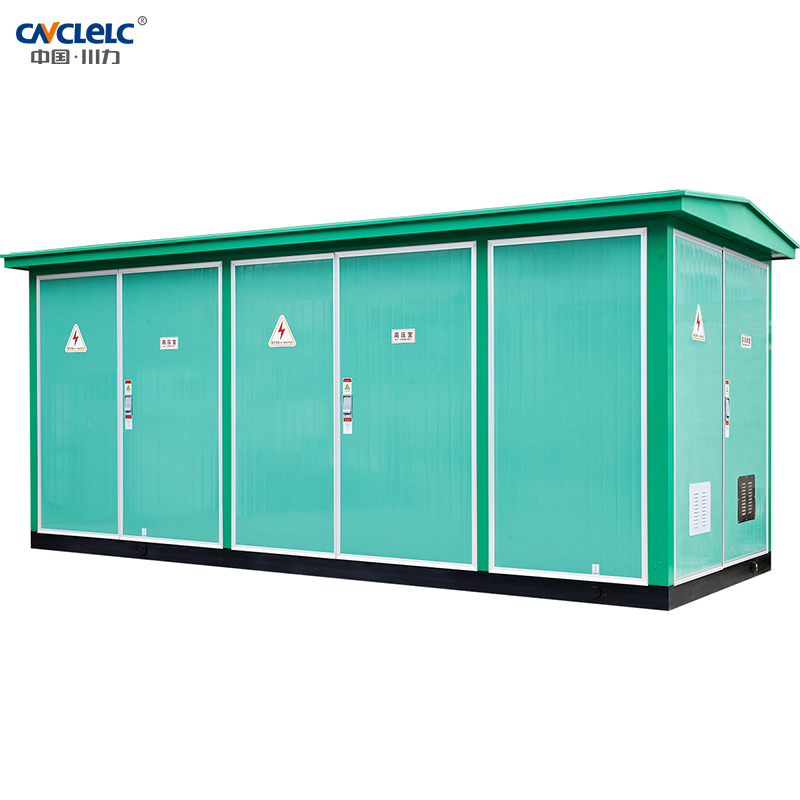
Product Overview: What Is the ZBW-12/0.4 Prefabricated Substation?
ZBW-12/0.4(F.R) Outdoor pre-installed substation (European), is a high-voltage switchgear distribution transformer and low-voltage distribution device, according to a certain wiring scheme arranged into one of the factory prefabricated indoor and outdoor compact distribution equipment, that is, high-voltage power, transformer, low-voltage distribution and other functions organically combined together. Installed in a moisture-proof, rust-proof, dust-proof, rat-proof, fi re-proof, anti-theft, spacer, fully enclosed, movable steel structure or non-metal box, mechatronics fully closed operation;
Widely used in urban power grid transformation, residential areas, high-rise buildings, industrial and mining, hotels, shopping malls, airports, railways, oil fields, docks, highways and temporary electricity facilities and other indoor and outdoor places.
Model Meaning
| ZBW | □ | | 12/0.4 | □ |
| ↓ | ↓ | | ↓ | ↓ |
| Pre-installed substation | Design sequence number | | Rated voltage (high/low voltage) | Transformer capacity |
Environmental Conditions Of Use
• Altitude does not exceed 2000m;
• Ambient temperature: -25℃ ~+40℃ ;
• Relative humidity: at 25℃ , the daily average is not more than 95%, the monthly average is not more than 90%;
• Installation site: no fire, explosion danger, conductive dust, chemical corrosive gas and violent vibration of the place, if beyond the above conditions, users can negotiate with our company.
Function & Characteristics
• High-voltage switchgear, distribution transformer, low-voltage switchgear power metering equipment and reactive power compensation device according to a certain scheme combination, complete sets of strong;
• Perfect high and low pressure protection, safe and reliable operation, simple maintenance;
• Small footprint, less investment, short production cycle, easy to move;
• Flexible wiring scheme;
• Unique structure: unique honeycomb structure double layer (composite board) shell is strong, heat insulation and heat dissipation ventilation, beautiful, high protection level, shell materials are stainless steel alloy, aluminum alloy, cold rolled plate, color steel plate optional;
• Various types: universal type, villa type, compact and other styles;
• High voltage ring network cabinet can be equipped with network automation terminal (FTU) to realize the reliable detection of short circuit and single-phase grounding fault, with “four remote” function, easy to upgrade the distribution network automation.
Transformer
Intelligent integrated substation selection of low loss, oil immersed, fully sealed S9, S10, S11 series transformers, can also choose resin insulation or NOMEX paper insulation environmentally friendly dry transformer, the bottom can be equipped with a car, the transformer can be convenient access.
High Pressure Side
Intelligent integrated substation high voltage generally adopts load switch-fuse combination electrical protection, fuse one phase of the fuse fuse, three-phase linkage trip, load switch has pressure type, vacuum, sulfur hexafluoride and other types of optional, can be equipped with electric operating mechanism, automation upgrade; Fuse is high voltage current limiting fuse, with impactor, reliable operation, large breaking capacity, the main technical parameters are shown in the following table. For transformers above 800kVA, ZN12, ZN28,VS1 and other vacuum circuit breakers can be used for protection.
Low Pressure Side
Low voltage side main switch adopts universal or intelligent circuit breaker, selective protection; The new type of plastic-case switch is selected as the outlet switch, which has small volume and short fly-arc, and can reach up to 30 circuits. Intelligent automatic tracking reactive power compensation device, there are contactor and contactless two switching modes for users to choose.
Enforce Standards
This product meets the following standards:
GB/T17467-1998 “High voltage/Low voltage pre-installed substation”
DL/T537-93 “6-35kV box-type substation ordering Technical Conditions”
Load Switch Technical Parameters
| Item | Units | FKN12-12 load switch | FZN12-12 Vacuum load switch |
| Rated voltage | kV | 10 | |
| Maximum operating voltage | kV | 12 | |
| Rated frequency | Hz | 50 | |
| Rated current | A | 630 | |
| Rated breaking load current | A | 630 | |
| Heat stable current | kA/S | 45708 | 45767 |
| Dynamic stable current | kA | 50 | 50 |
| Short-circuit closing current (peak) | kA | 50 | 50 |
| Full load breaking times | time | 20 | 10000 |
| Mechanical life | time | 2000 | 10000 |
| 1min power frequency withstand voltage(phase to phase and ground) | kV | 42 | 42 |
| Lightning impulse voltage (relative and to ground) | kV | 75 | 75 |
Technical Parameters Of High Voltage Fus
| Model number | Rated | Breaking
current(A) | Breaking
current(kA) | Rated current of melt(A) |
| British model | Domestic model | voltage(kV) |
| SDL※J | XRNT-12 | 12 | 40 | 31.5 | 6.3,10,16,20,25,31.5,40 |
| SFL※J | XRNT-12 | 12 | 100 | 31.5 | 50,63,71,80,100 |
| SKL※J | XRNT-12 | 12 | 125 | 31.5 | 125 |
*Note:Determined by whether an impactor is installed,N means no firing pin and A means there is a firing pin.
| Model number | Release form | Rated current of the release A | On-off capacity kA(AC380V) |
| DW15-630 | Thermo-electromagnetic or electronic type | 315,400,630 | 40 |
| DW15-1000 | Thermo-electromagnetic or electronic type | 630,800,1000 | 50 |
| DW15-1600 | Thermo-electromagnetic or electronic type | 1600 | 50 |
| DW15-2500 | Thermo-electromagnetic or electronic type | 1600,2000,2500 | 60 |
| CW1-2000 | intelligent | 630,800,1000,1250,1600,2000 | 65(80) |
| CW1-3200 | intelligent | 2000,2500,3200 | 100 |
Note: (80) polymer fracture type.
Primary Plan Drawing
The substation primary scheme is shown in the attached drawing.
Example Diagram Of A Typical Scheme
See the attached figure for an example of a typical scheme.
Foundation And Floor Plan
The basic drawing of substation is referred to the attached drawing. Thelayout of substation is shown in the attached drawing, and users can choose according to their needs.
Installation, Use And Maintenance
In addition to the requirements of the power department in terms of installation, acceptance, handover test, operation and maintenance, intelligent integrated substation should pay attention to the following matters:
● When the user receives the goods, it should be carefully checked according to the relevant regulations. For the products that are not installed immediately, they should be stored in the appropriate place according to the normal conditions of use.
● The product should be lifted at the bottom of the special spreader, as shown in Figure 3.
● The product is placed horizontally on a pre-made basis, and then the gap between the product base and the foundation is sealed with cement slurry to prevent rain from entering the cable room, and the high and low voltage cables are accessed through the bottom sealing plate of the high and low pressure chambers.
● The product should be reliably grounded after installation; The two main ground terminals on the channel steel of the power station base, the neutral point of the transformer and the shell, and the pile head under the arrester should be grounded respectively by the installation department. All grounding devices should share a set of grounding devices, the grounding resistance should be less than 4 ohms;
● After the installation or maintenance of the product, the following items should be inspected and tested before operation:
○ Whether the substation is clean;
○ Whether the operating mechanism is flexible;
○ Whether the main electrical appliances are flexible and reliable;
○ Whether the electrical auxiliary contact is reliable and accurate;
○ Whether the meter and relay operation are accurate;
○ Whether the ratio and wiring polarity of the instrument and transformer are correct;
○ Whether all electrical installation nuts are tightened, whether the installation is firm and reliable;
○ Whether the bus is well connected, its support insulator, whether the clamp is installed reliably;
○ Whether the setting value of the electrical appliance meets the requirements and whether the melt core specification of the fuse is correct:
○ Whether the contacts of the main circuit and auxiliary circuit meet the requirements of the electrical schematic diagram.
● Maintenance
○ All components in the product are maintained according to their respective technical requirements:
○ If the selected transformer is oil-immersed, the oil sample analysis should be checked at least once a year according to the regulations;
○ High voltage side switchgear in operation, after 20 times with load or 2000 times without load opening and closing operation, should check the contact condition and loss degree of arc extinguishing device, found abnormal should be repaired or replaced in time.
○ Low-voltage switchgear automatic trip, should check and analyze the cause of the trip, after troubleshooting, can be put into operation again;
○ The arrester should be carried out a preventive test every year before the thunderstorm season;
Note: Packing list, certificate of qualification, installation instruction manual, electrical wiring diagram, instructions of the main components and equipment used in this product, key operation tools and spare parts provided in accordance with the agreement are attached.
FAQs
What is the ZBW-12/0.4(F.R) prefabricated substation and where is it typically used?
The ZBW-12/0.4(F.R) is a European-type outdoor prefabricated (compact) substation that integrates a 12kV high-voltage switchgear, distribution transformer, and low-voltage distribution panel into a single factory-assembled enclosure. It is widely deployed in urban power grid upgrades, residential communities, high-rise buildings, industrial parks, airports, railways, mining sites, and temporary power supply facilities. If you need a compact, ready-to-install substation solution with minimal on-site civil construction, the ZBW-12/0.4 is an efficient choice for your project.
What compliance standards does the ZBW-12/0.4 prefabricated substation meet?
The ZBW-12/0.4 is designed and tested to comply with GB/T17467-1998 “High Voltage / Low Voltage Pre-installed Substation” and DL/T537-93 “6–35kV Box-Type Substation Ordering Technical Conditions.” These standards govern the design, safety, and performance requirements for compact substations used in Chinese and international power distribution networks. Certified test reports are available upon request when you submit your project inquiry.
What transformer types can be installed in the ZBW-12/0.4 substation?
The ZBW-12/0.4 is compatible with multiple transformer types to suit your project requirements. Standard configurations support low-loss oil-immersed transformers of the S9, S10, and S11 series (fully sealed). For environmentally sensitive or indoor-adjacent installations, resin-insulated (cast resin) dry-type transformers and NOMEX paper-insulated dry transformers are also available. Transformer capacities and vector groups can be customized. Contact our technical team to discuss the optimal transformer specification for your load profile.
What are the installation site and environmental requirements for this substation?
The ZBW-12/0.4 is designed for outdoor installation at altitudes up to 2000m. The ambient temperature range is −25°C to +40°C, with relative humidity not exceeding 95% (daily average at 25°C) or 90% (monthly average). Installation sites must be free from fire hazards, explosive atmospheres, conductive dust, chemically corrosive gases, and severe vibration. For projects that fall outside these standard conditions — such as high-altitude, coastal, or chemically aggressive environments — please contact us to discuss customized enclosure protection ratings and material options.
Can the ZBW-12/0.4 substation support distribution network automation (FTU)?
Yes. The ZBW-12/0.4 can be equipped with a network automation terminal (FTU) on the high-voltage ring main unit side, enabling reliable detection of short-circuit and single-phase earth faults. This configuration supports “four remote” functions (remote monitoring, remote control, remote measurement, and remote signaling), making it compatible with smart grid and distribution automation upgrades. If your utility or EPC project requires SCADA integration or specific communication protocols, our engineering team can assist with the automation specification.
 跳到内容
跳到内容