ZW32-24 Interruptor automático de vacío para exteriores
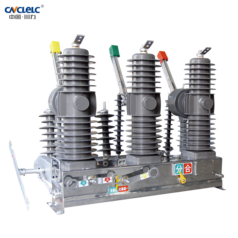
El disyuntor de vacío de media tensión para exteriores ZW32-24 (en lo sucesivo, el disyuntor) es un equipo de distribución para exteriores con una tensión nominal de 24 kV, CA trifásica de 50 Hz. Se utiliza principalmente para cortar y cerrar la corriente de carga, la corriente de sobrecarga y la corriente de cortocircuito del sistema eléctrico. Se aplica a la subestación y las empresas industriales y mineras en el sistema de energía para la protección y el control de uso, más adecuado para la red eléctrica rural y el lugar de operación frecuente.
El disyuntor de vacío de media tensión para exteriores ZW32-24 (en lo sucesivo, el disyuntor) es un equipo de distribución para exteriores con una tensión nominal de 24 kV, CA trifásica de 50 Hz. Se utiliza principalmente para cortar y cerrar la corriente de carga, la corriente de sobrecarga y la corriente de cortocircuito del sistema eléctrico. Se aplica a la subestación y las empresas industriales y mineras en el sistema de energía para la protección y el control de uso, más adecuado para la red eléctrica rural y el lugar de operación frecuente.
Modelo Significado
ZW
32
24
1
T
630
20
G
□
↓
↓
↓
↓
↓
↓
↓
↓
En el exterior
Vacío
Circuito
Interruptor
Diseño
secuencia
número
Rated
tensión(kV)
Munición
manejo de
mecanismo
Rated
corriente(A)
Rated
cortocircuito
rompiendo
corriente(kA)
Cinta
aislamiento
S mano
ejercicio
Delectric
ejercicio
Norma de cotización
1. Disyuntor de alta tensión CA GB 1984-2003
2. GB 3309-1989 Ensayo mecánico de aparamenta de alta tensión a temperatura ambiente.
3. GB 5582-1993 Nivel de contaminación de los equipos eléctricos aislantes de alta tensión
4. GB 1985-2004 Interruptor de aislamiento de alta tensión de CA y seccionador de puesta a tierra
5. GB/T 11022-1999 Requisitos técnicos comunes para equipos de conmutación de alta tensión y equipos de control.
6. GB 16927.1-1997 Primera parte de las técnicas de ensayo de alta tensión: Requisitos generales de ensayo
7. DL/T 402-2007 Condiciones técnicas para el pedido de disyuntores de alta tensión CA
8. DL/T 593-2006 Especificación técnica común de las normas relativas a los equipos de conmutación de alta tensión y a los equipos de control.
Principales parámetros técnicos
Tensión nominal
kV
24
Aislamiento nominal
nivel
1 min de potencia
frecuencia soportada
tensión
Prueba en seco
kV
65/79(fractura de aislamiento)
Prueba en húmedo
kV
50/64(fractura de aislamiento)
El circuito auxiliar y el circuito de control
kV
2
Tensión soportada por impulso de rayo (pico)
kV
125/145(fractura de aislamiento)
Frecuencia nominal
Hz
50
Corriente nominal
A
6301250
Secuencia de funcionamiento nominal
O-0,3s-CO-180s-CO
Corriente asignada de corte en cortocircuito
kA
16 20
25
Corriente nominal de cierre en cortocircuito (pico)
kA
40 50
63
Corriente nominal de pico soportada
kA
40 50
63
Corriente nominal de corta duración
kA
16 20
25
Duración nominal del cortocircuito
S
4
Tiempos asignados de corriente de corte en cortocircuito
Times
20/25
Tiempos de ruptura de la corriente nominal
Times
10000
Hora de cierre
ms
20~80
Bajo tensión máxima de funcionamiento
ms
20~80
Hora de apertura
Tensión de funcionamiento por debajo de la nominal
ms
20~80
Con la tensión de funcionamiento más baja
ms
20~80
Jornada completa
Times
≤100
Vida mecánica
J
10000
Conectar la alimentación
W
70
Potencia nominal de entrada del motor de almacenamiento de energía
V
≤70
Tensión nominal de funcionamiento y tensión nominal de los circuitos auxiliares
V
CC,CA 220
Tiempo de almacenamiento de energía bajo tensión nominal
S
≤8
Liberación por sobreintensidad
Corriente nominal
A
5
Precisión de la corriente de disparo
%
±10
Una vez montado y ajustado, el disyuntor debe cumplir los requisitos de la tabla 2.
ltem
Unidad
Parámetro
Espacio abierto entre contactos
mm
13±1
Contactar con overtravel
mm
3±1
Velocidad media de apertura
m/s
1.5±0.2
Velocidad media de cierre
m/s
0.8±0.2
Tiempo de rebote al cerrar el contacto
ms
≤3
Disparo trifásico durante el mismo periodo de tiempo
ms
≤2
Resistencia CC del circuito para cada fase (con interruptor de aislamiento)
μΩ
≤60(150)
Espesor de desgaste admisible para contacto dinámico y estático
mm
3
Distancia entre centros de fase
mm
380±1.5
La presión nominal del muelle de contacto en estado de cierre
N
2000±200
Interruptor automático equipado Interruptor de aislamiento Parámetros nominales
ltem
Unidad
Parámetro
Tensión nominal
KV
24
Frecuencia nominal
Hz
50
Corriente nominal
A
1250
Corriente nominal de pico soportada
kA
50
Corriente nominal de corta duración
kA
20
Duración nominal del cortocircuito
S
4
Vida mecánica
Times
2000
Par de operación de fractura del interruptor de aislamiento
N*m
≤300
Presión del muelle de la hoja de contacto
N
300±30
Estática nominal de los bornes
carga mecánica
Carga longitudinal horizontal
N
500
Carga transversal horizontal
N
250
Fuerza vertical
N
300
Condiciones de funcionamiento
1. Temperatura del aire ambiente: La variación diaria de la temperatura: -40℃ ~+40℃ variación diurna de la temperatura inferior a 25℃;
2. Altitud: no más de 2000 metros
3. La velocidad del viento no es superior a 35 m/s (equivalente a 700Pa en la superficie del cilíndrico);
4. Espesor de la capa de hielo no superior a 10 mm;
5. La intensidad de la luz solar no es superior a 1000W/m ².
6. Grado de contaminación no superior a GB 5582 IV clase
7. La intensidad sísmica no supera la clase 8
8. No inflamable, explosivo, corrosión química y lugar de vibración severa.
9. las condiciones de uso superan las normas antes mencionadas, se determinará mediante consulta entre el usuario y el fabricante.
Dimensiones
Dimensiones generales y de montaje (mm)
1. salida inferior
2. transformador de corriente
3. Entrada superior
4. Pilar aislante
5. El interruptor de vacío
6. guías de alambre
7. conexión flexible
8. Poste de tensión aislado
9. actuador
10. caso
ESTAMOS AQUÍ PARA APOYARLE
¿Desea más información o una consulta personal? Nuestros productos y conocimientos
están ahí para ofrecerle soluciones.
 Ir al contenido