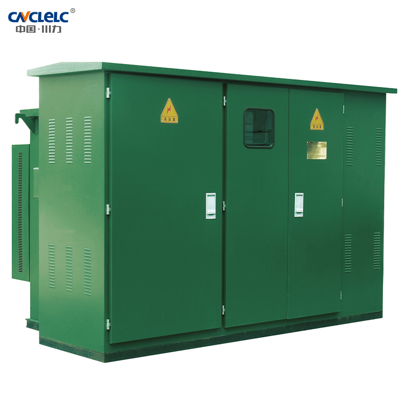
ZBW series preassembled box-type substation (commonly known as American box-type transformer), its structure is “product” font structure, the transformer and high and low voltage equipment are closely connected as one, among which, three sides of the transformer exposed to the air, good heat dissipation conditions, and can be separated from the high and low voltage equipment housing, easy maintenance.
ZBW series preassembled box-type substation (commonly known as American box-type transformer), its structure is “product” font structure, the transformer and high and low voltage equipment are closely connected as one, among which, three sides of the transformer exposed to the air, good heat dissipation conditions, and can be separated from the high and low voltage equipment housing, easy maintenance.
The 813 series oil-immersed transformer with chip type oil tank, no oil cushion, fully enclosed, high and low pressure bushing, tap changer, oil level indicator, pressure release valve, oil release valve, etc. are installed on the end plate of the high-pressure chamber body, the position is reasonable, easy to observe and operate. The high-pressure chamber and low-pressure chamber are separated by steel plates. The high-pressure chamber and low-pressure chamber transformers are relatively independent and maintain a complete box as a whole, with compact structure, small volume and light weight. The power distribution switchgear is installed on the high and low voltage sides.
Model Meaning
ZBW
□
–
□
–
□
/
□
↓
↓
↓
↓
↓
Pre-installed substation
Performance level code
High voltage connection scheme
Rated capacity of transformer
Voltage level
Environmental Conditions Of Use
Cooling condition: air self-cooling
Use Environment:
The outdoor ambient temperature is not higher than 40℃ , not lower than -45℃ , the altitude is not more than 1000m, the monthly average temperature is not more than 30℃ , the annual average temperature is not more than 20℃ ; At 25℃ , the relative humidity of the air does not exceed 95%, and the monthly average does not exceed 90%;
• Horizontal acceleration is not more than 0.3g, vertical acceleration is not more than 0.15g;
• The installation environment should be free from obvious pollution, no explosive, corrosive gas and dust, and the installation site should be free from violent vibration and impact, requiring the installation on a cement platform or other flat and solid platform.
Note: In case of any other violation of this technical regulation, the user shall negotiate with the Company
Product Characteristics
• Small size, compact structure, easy installation:
• Can be used for ring network, can also be used for terminal, reliable protection of personal safety
• Low loss, low noise, superior performance;
• The box adopts anti-theft structure;
• Low temperature rise, strong overload capacity
Enforce Standards
This product meets the following standards:
GB/T17467-1998 “High voltage/Low voltage pre-installed substation”
Selected new S9 series transformer body, low loss, good overload capacity, strong short-circuit resistance, all fasteners are protected. The S11 series ring jointless core transformer with better performance can also be selected.
Capacity KVA
Voltage KV
Join group label
No-load current %
No load loss W
Impedance voltage %
Load loss
High tension
Low pressure
S9
S10
S11
S9
S10
S11
160
10±5% or 2×2.5%
0.4
Dyn11 Y.yno
1.4
1.4
0.2
400
320
255
2200
200
1.3
1.3
0.2
480
380
305
2600
250
1.2
1.2
0.2
560
450
360
3050
315
1.1
1.1
0.2
670
530
425
4.0
3650
400
1.0
1.0
0.15
800
650
505
4300
500
1.0
1.0
0.15
960
750
605
5100
630
0.9
0.9
0.15
1200
910
755
6200
800
0.8
0.8
0.15
1400
1080
980
4.5
7500
1000
0.7
0.7
–
1700
1260
–
10300
1250
0.6
0.6
–
1950
–
–
12000
Fuse
The full range of protection is provided by the backup protection fuse and the plug-in fuse in series on the high voltage side of the American box, the principle is simple, economical and reliable; Backup protection fuse is oil-immersed high voltage current limiting fuse, breaking capacity is large, only in the transformer internal fault action plug-in fuse equipped with double sensitive fuse, can provide current and temperature double protection, after the double sensitive fuse is blown, can be easily replaced in the field.
Load Switch
Load switch is oil-immersed, three-phase linkage switch, spring operating mechanism; It can be operated with load, and its closing speed has nothing to do with the operating force. There are two stations, four stations T type, four T position V type, etc., to choose from.
Item
Name
Units
315A
630A
Rated voltage
KV
12
12
Maximum current
A
315
630
Rated frequency
Hz
50
50
Rated short-circuit closing current
kA
31.5
50
Rated short-time withstand current
kA
12.5
50
Rated short endurance time
S
2
2
Mechanical life
frequency
2000
2000
Lightning impulse test
Phase to phase
KV
75
75
Isolation fracture
85
85
1min power frequency
withstand voltage
Phase to phase
KA
42
42
Isolation fracture
48
48
Rated peak withstand current
KV
31.5
50
Outline Mounting Dimension(mm)
Capacity
A
B
C
H
Weight KG
200kVA and below
1830
1420
820
1850
≤2800
250-400kVA
1830
1450
850
1980
3000-3300
500-630kVA
1830
1480
880
2070
3600-3950
800kVA
2200
1700
950
2170
4500
Note: The above is the standard size for reference.
Capacity
A
B
C
H
Weight KG
315kVA
2560
1600
600
1000
3050
400kVA
2560
1600
600
1000
3270
500kVA
2560
1600
600
1000
3400
630kVA
2560
1600
600
1000
3900
800kVA
2760
1600
800
1000
4200
1000kVA
2760
1950
800
1000
4800
1250kVA
2910
1950
800
1000
5400
1600kVA
2200
1700
950
2170
4500
Note: The above is the standard size for reference.
Mounting Dimension(mm)
Technical Requirement
• The surface of the concrete base should be flat, and after the installation of the combined substation, the base should be sealed with cement around;
• The shape of the ground bar and cable fixing bracket can be determined according to the actual situation;
• Cable fixing frame and ground bar should be embedded;
• The position of the inlet and outlet cable holes depends on the specific situation;
• There must be a gap of not less than 1.5m on the front of the switch after installation of the combination transformer to facilitate operation;
• The grounding net can be made of 12-plated round steel or 30×4 galvanized flat steel, and the grounding wire resistance should meet the requirements of the power department.
Foundation Drawing
• Standard type, enhanced type, basic construction requirements.
• The basic endurance is more than 100kPa.
• The foundation is located at a higher elevation, drained outwards on all sides, and constructed with red brick cement mortar. The inner and outer walls shall be coated with 1:2 cement mortar 20mm thick and mixed with 3% waterproofing agent.
• The bottom of the cable room should be slightly inclined to the side of the collection pipe to avoid water accumulation.
• 150×300 steel plate mesh (10×20) diamond-shaped eyes are welded on the inside side of the louver window frame, and the welding bar claws are embedded in the wall.
• Foundation construction shall comply with the relevant provisions of JGJ/T16-92 “Code for Electrical Design of Civil Construction”.
• The practice of grounding trunk and grounding pole is still done as usual. After the grounding trunk is drawn from the cable trench, it can be arranged around the ring network cabinet, or the grounding pole can be extended from one side. Grounding resistance ≤ 40Ω.
• The dimensions in the figure are recommended values.
• In order to facilitate the user to enter the line, the cable can be set in three or four directions according to the actual situation on the site.
Typical Scheme
High-pressure Typical Scheme
Scheme number
H-01
H-02
H-03
H-04
H-05
Single line diagram of main loop
10kV power supply I
10kV power supply I 10kV power supply Il
10kV power supply I 10kV power supply II
Type
Terminal type with two-position load switch.
The ring network type is changed,and the four-position “V”type load switch is adopted.
The ring network type is changed,and the four-position “T”type load is opened close.
The terminal type uses a four-position “V” type and a two-station load switch.
Terminal type with high voltage metering function.
Switch selection
Single power supply,suitable for end users
Ring network or dual power supply can be realized,but when the transformer is disconnected,the high- voltage power supply l and high-voltage power supply II are disconnected at the same time;Applicable ring network current 315A,630A.
It can realize the ring network or dual power supply,but when the transformer is disconnected,the high-voltage power supply l and high-voltage power supply Il are not connected to each other.Applicable ring network current 315A,630A.
The scope of application can realize the ring network or dual power supply, is the most perfect ring network scheme, the selection of ring network current 315A, 630A.
Suitable for users requiring high voltage metering
Low Pressure Typical Scheme
Scheme number
L01
L02
L03
L04
L05
L06
Single line diagram of main loop
Type
Switch selection
Main switch, total metering (active and reactive power), two branch active power metering, 63-1250A, optional undervoltage controller, suitable for all capacities.
Main switch, total metering (active, reactive power), outlet 63-1250A, optional undervoltage controller, suitable for all capacities.
Main switch, total metering (active, reactive power), output line 63-1250A reactive power compensation 30-360kVar, optional undervoltage controller, suitable for all capacities.
Main switch, total metering (active, reactive power) line 63-1250A, optional undervoltage controller, switching device use intelligent composite switch and capacitive contactless switch. Applicable to all capacities.
Main switch, total measurement (active, reactive power), outlet 63-1250A, optional undervoltage controller, compensation for total complement, sub complement. Applicable to all capacities.
Main switch, total measurement (active, reactive power), out of 63-1250A reactive power compensation 30-360kVar, optional undervoltage controller, compensation for compensating. Applicable to all capacities
WE ARE HERE TO SUPPORT YOU!
Further information or a personal consultation? Our products and know-how
are there to provide solutions.
 跳到内容
跳到内容