Le transformateur et l'équipement haute et basse tension sont étroitement liés. Trois côtés du transformateur sont exposés à l'air, ce qui permet de bonnes conditions de dissipation de la chaleur, et peut être séparé du boîtier de l'équipement haute et basse tension, ce qui facilite la maintenance.
Le transformateur et l'équipement haute et basse tension sont étroitement liés. Trois côtés du transformateur sont exposés à l'air, ce qui permet de bonnes conditions de dissipation de la chaleur, et peut être séparé du boîtier de l'équipement haute et basse tension, ce qui facilite la maintenance.
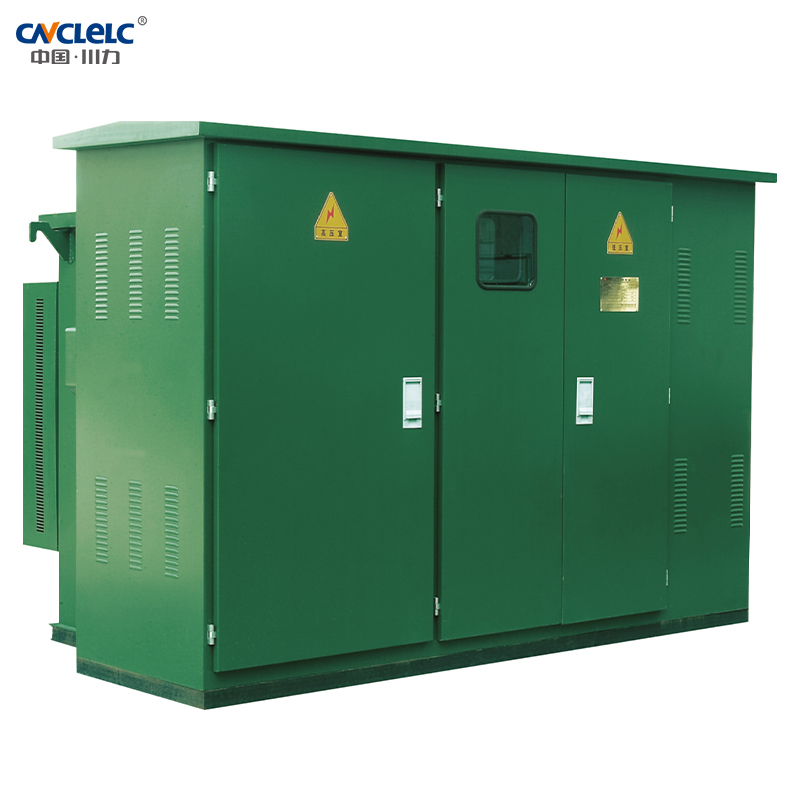
Le transformateur à bain d'huile de la série 813 est équipé d'un réservoir d'huile à puce, sans coussin d'huile, entièrement fermé. Les douilles haute et basse pression, le changeur de prise, l'indicateur de niveau d'huile, la soupape de décharge de pression, la soupape de décharge d'huile, etc. sont installés sur la plaque d'extrémité du corps de la chambre haute pression, la position est raisonnable, facile à observer et à faire fonctionner. La chambre haute pression et la chambre basse pression sont séparées par des plaques d'acier. Les transformateurs de la chambre haute pression et de la chambre basse pression sont relativement indépendants et forment un ensemble complet, avec une structure compacte, un petit volume et un poids léger. L'appareillage de distribution électrique est installé du côté de la haute et de la basse tension.
Signification du modèle
ZBW
□
–
□
–
□
/
□
↓
↓
↓
↓
↓
Sous-station préinstallée
Code de niveau de performance
Schéma de connexion à la haute tension
Capacité nominale du transformateur
Niveau de tension
Conditions environnementales d'utilisation
Condition de refroidissement : auto-refroidissement par air
Environnement d'utilisation :
La température ambiante extérieure n'est pas supérieure à 40℃ , pas inférieure à -45℃ , l'altitude n'est pas supérieure à 1000m, la température moyenne mensuelle n'est pas supérieure à 30℃ , la température moyenne annuelle n'est pas supérieure à 20℃ ; A 25℃ , l'humidité relative de l'air n'excède pas 95%, et la moyenne mensuelle n'excède pas 90% ;
- L'accélération horizontale ne dépasse pas 0,3 g, l'accélération verticale ne dépasse pas 0,15 g ;
- L'environnement d'installation doit être exempt de pollution évidente, de gaz explosifs et corrosifs et de poussière, et le site d'installation doit être exempt de vibrations et d'impacts violents, ce qui nécessite l'installation sur une plate-forme en ciment ou une autre plate-forme plate et solide.
Note : En cas d'autre violation de cette règle technique, l'utilisateur doit négocier avec l'entreprise.
Caractéristiques du produit
- Petite taille, structure compacte, installation facile :
- Peut être utilisé pour le réseau en anneau, peut également être utilisé pour le terminal, protection fiable de la sécurité personnelle
DL/T537-93 "Conditions techniques pour la commande d'une sous-station de type boîte 6-35kV".
Principaux paramètres techniques
Numéro de série
Objet
Unités
Paramètres techniques
1
Tension nominale
KV
10/0,4 (haute/basse pression)
2
Tension de fonctionnement maximale
KV
12(côté haute pression)
3
Fréquence nominale
Hz
50
4
Capacité nominale
KVA
150-1600.
5
1min fréquence d'alimentation tension de résistance
KV
35
6
Tension d'impulsion de la foudre
KV
75
7
Mode de refroidissement
Huile immergée dans un système de refroidissement automatique
8
Courant de rupture du fusible de secours à haute tension
KA
50
9
Courant de rupture du fusible enfichable
KA
2.5
10
Température ambiante
℃
-35~+40
11
Le serpentin permet une augmentation de la température
k
65
12
Régulation de la tension à vide
±5%ou±2×2.5%
13
Niveau sonore
db
50
14
Classe de protection
KV
IP43
Transformateur
Le nouveau corps du transformateur de la série S9 a été sélectionné. Il présente de faibles pertes, une bonne capacité de surcharge, une forte résistance aux courts-circuits et toutes les fixations sont protégées. Le transformateur à noyau annulaire sans joint de la série S11, plus performant, peut également être sélectionné.
Capacité KVA
Tension KV
Rejoindre le groupe étiquette
Courant à vide %
Perte à vide W
Impédance tension %
Perte de charge
Haut tension
Faible pression
S9
S10
S11
S9
S10
S11
160
10±5% ou 2×2,5%
0.4
Dyn11 Y.yno
1.4
1.4
0.2
400
320
255
2200
200
1.3
1.3
0.2
480
380
305
2600
250
1.2
1.2
0.2
560
450
360
3050
315
1.1
1.1
0.2
670
530
425
4.0
3650
400
1.0
1.0
0.15
800
650
505
4300
500
1.0
1.0
0.15
960
750
605
5100
630
0.9
0.9
0.15
1200
910
755
6200
800
0.8
0.8
0.15
1400
1080
980
4.5
7500
1000
0.7
0.7
–
1700
1260
–
10300
1250
0.6
0.6
–
1950
–
–
12000
Fusible
La gamme complète de protection est assurée par le fusible de protection de secours et le fusible enfichable en série du côté haute tension de la boîte américaine, le principe est simple, économique et fiable ; le fusible de protection de secours est un fusible limiteur de courant haute tension à bain d'huile, le pouvoir de coupure est important, uniquement en cas de défaut interne du transformateur le fusible enfichable est équipé d'un fusible à double sensibilité, il peut fournir une double protection de courant et de température, après que le fusible à double sensibilité ait sauté, il peut être facilement remplacé sur le terrain.
Interrupteur de charge
Les interrupteurs de charge sont des interrupteurs à bain d'huile, à tringlerie triphasée, à mécanisme de fonctionnement à ressort ; ils peuvent être actionnés avec une charge, et leur vitesse de fermeture n'a rien à voir avec la force d'actionnement. Il est possible de choisir entre deux stations, quatre stations de type T, quatre positions T de type V, etc.
Objet
Nom
Unités
315A
630A
Tension nominale
KV
12
12
Courant maximum
A
315
630
Fréquence nominale
Hz
50
50
Courant nominal de fermeture en cas de court-circuit
kA
31.5
50
Courant nominal de courte durée
kA
12.5
50
Durée d'endurance nominale courte
S
2
2
Durée de vie mécanique
fréquence
2000
2000
Test d'impulsion de foudre
Phase à phase
KV
75
75
Fracture d'isolement
85
85
1min fréquence d'alimentation
tension de résistance
Phase à phase
KA
42
42
Fracture d'isolement
48
48
Courant de résistance nominal de crête
KV
31.5
50
Dimension de montage (mm)
Capacité
A
B
C
H
Poids KG
200kVA et moins
1830
1420
820
1850
≤2800
250-400kVA
1830
1450
850
1980
3000-3300
500-630kVA
1830
1480
880
2070
3600-3950
800kVA
2200
1700
950
2170
4500
Note : La taille ci-dessus est la taille standard à titre de référence.
Capacité
A
B
C
H
Poids KG
315kVA
2560
1600
600
1000
3050
400kVA
2560
1600
600
1000
3270
500kVA
2560
1600
600
1000
3400
630kVA
2560
1600
600
1000
3900
800kVA
2760
1600
800
1000
4200
1000kVA
2760
1950
800
1000
4800
1250kVA
2910
1950
800
1000
5400
1600kVA
2200
1700
950
2170
4500
Note : La taille ci-dessus est la taille standard à titre de référence.
Dimension de montage (mm)
Exigences techniques
- La surface de la base en béton doit être plane et, après l'installation de la sous-station combinée, la base doit être scellée avec du ciment ;
- La forme de la barre au sol et du support de fixation du câble peut être déterminée en fonction de la situation réelle ;
- Le cadre de fixation des câbles et la barre de terre doivent être encastrés ;
- La position des trous pour les câbles d'entrée et de sortie dépend de la situation spécifique ;
- Après l'installation du transformateur combiné, il doit y avoir un espace d'au moins 1,5 m à l'avant de l'interrupteur pour en faciliter le fonctionnement ;
- Le filet de mise à la terre peut être en acier rond plaqué 12 ou en acier plat galvanisé 30×4, et la résistance du fil de mise à la terre doit être conforme aux exigences du service de l'électricité.
Dessin de fondation
- Type standard, type amélioré, exigences de base en matière de construction.
- L'endurance de base est supérieure à 100kPa.
- La fondation est située à une hauteur plus élevée, drainée vers l'extérieur de tous les côtés et construite avec du mortier de ciment en briques rouges. Les murs intérieurs et extérieurs sont recouverts d'un mortier de ciment 1:2 de 20 mm d'épaisseur mélangé à l'agent imperméabilisant 3%.
- Le fond de la chambre des câbles doit être légèrement incliné du côté du tuyau de collecte afin d'éviter l'accumulation d'eau.
- Des œillets en forme de diamant de 150×300 plaques d'acier (10×20) sont soudés sur le côté intérieur du cadre de la fenêtre à persiennes, et les griffes de la barre de soudure sont encastrées dans le mur.
- La construction des fondations doit être conforme aux dispositions pertinentes du document JGJ/T16-92 "Code for Electrical Design of Civil Construction".
- La pratique du tronc de mise à la terre et du piquet de mise à la terre reste habituelle. Une fois le tronc de mise à la terre tiré de la tranchée du câble, il peut être disposé autour de l'armoire du réseau en anneau, ou le poteau de mise à la terre peut être prolongé d'un côté. Résistance de mise à la terre ≤ 40Ω.
- Les dimensions indiquées dans la figure sont des valeurs recommandées.
- Afin de faciliter l'entrée de l'utilisateur dans la ligne, le câble peut être orienté dans trois ou quatre directions en fonction de la situation réelle sur le site.
Schéma type
Haute pression Schéma typique
Numéro du régime
H-01
H-02
H-03
H-04
H-05
Schéma unifilaire de la boucle principale
Alimentation 10kV I
Alimentation 10kV I Alimentation 10kV Il
Alimentation 10kV I Alimentation 10kV II
Type
Type de borne avec interrupteur de charge à deux positions.
Le type de réseau en anneau est modifié et le commutateur de charge à quatre positions de type "V" est adopté.
Le type de réseau en anneau est modifié, et la charge de type "T" à quatre positions est ouverte et fermée.
Le type de borne utilise un type "V" à quatre positions et un interrupteur de charge à deux positions.
Type de borne avec fonction de mesure de la haute tension.
Sélection de l'interrupteur
Alimentation électrique unique, adaptée aux utilisateurs finaux
Il est possible de réaliser un réseau en anneau ou une double alimentation, mais lorsque le transformateur est déconnecté, l'alimentation haute tension I et l'alimentation haute tension II sont déconnectées en même temps ; le courant applicable au réseau en anneau est de 315A, 630A.
Il peut réaliser le réseau en anneau ou l'alimentation double, mais lorsque le transformateur est déconnecté, l'alimentation haute tension l et l'alimentation haute tension Il ne sont pas connectées l'une à l'autre.315A,630A de courant de réseau en anneau applicable.
Le champ d'application peut réaliser le réseau en anneau ou l'alimentation double, c'est le schéma de réseau en anneau le plus parfait, la sélection du courant de réseau en anneau 315A, 630A.
Convient aux utilisateurs qui ont besoin de compteurs à haute tension
Schéma type basse pression
Numéro du régime
L01
L02
L03
L04
L05
L06
Schéma unifilaire de la boucle principale
Type
Sélection de l'interrupteur
Interrupteur principal, comptage total (puissance active et réactive), comptage de la puissance active sur deux branches, 63-1250A, contrôleur de sous-tension en option, adapté à toutes les capacités.
Interrupteur principal, comptage total (puissance active, réactive), prise 63-1250A, contrôleur de sous-tension en option, adapté à toutes les capacités.
Interrupteur principal, comptage total (puissance active, réactive), ligne de sortie 63-1250A, compensation de la puissance réactive 30-360kVar, contrôleur de sous-tension en option, adapté à toutes les capacités.
Interrupteur principal, ligne de comptage total (puissance active, réactive) 63-1250A, contrôleur de sous-tension en option, dispositif de commutation utilisant un interrupteur composite intelligent et un interrupteur capacitif sans contact. Applicable à toutes les capacités.
Interrupteur principal, mesure totale (puissance active, réactive), prise 63-1250A, contrôleur de sous-tension en option, compensation du complément total, sous-complément. Applicable à toutes les capacités.
Interrupteur principal, mesure totale (puissance active, réactive), compensation de la puissance réactive de 63-1250A 30-360kVar, contrôleur de sous-tension optionnel, compensation pour la compensation. Applicable à toutes les capacités
NOUS SOMMES LÀ POUR VOUS SOUTENIR !
Plus d'informations ou une consultation personnelle ? Nos produits et notre savoir-faire
sont là pour apporter des solutions.
 Skip to content