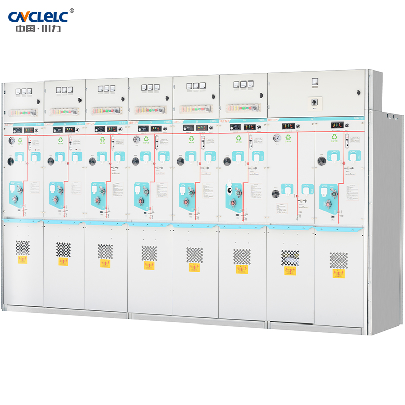
MGA series eco-friendly gas insulated AC metal-enclosed switchgear and control equipment (hereinafter referred to as MGA series switchgear)is an environmentfriendly gas-insulated medium-voltage switchgear developed independently by Chuanli. It features green and environmentally friendly, reliable performance, guaranteed safety, compact design, small footprint, maintenance-free operation, long lifespan, and strong adaptability to various environmental conditions.
MGA series eco-friendly gas insulated Ac meta-enclosed switchgear and control equipment (hereinafter referred to as MGA series switchgearis anenvironmentriendly gas-insulated medium-voltage switchgear developed independenlly by Chuani. lt features green and environmentaly frniendly.reliable performance, quaranteed safely, compact desion, smallfootoint, maintenance-fee operalion, long fespan, and strong adaptabilty to varousenvironmental conditions.
The MGA series switchgear is a fuly sealed system, with all primary components and switches endosed within a stainless steel shell, which is notaffected by the environment. The product adopts a modular design, aowing for flexible arrangement according to diferent design schemes, enablingcombinations of compact and expandable units to meet the requirements of various secondary distribution substations for compact switchgearThe MGA series switchaear has passed the type tests conducted by the nationalevel hioh-voltage electical apparatus tesing center, making it suitablfor a wide range of applicaions, including smal-scale secondary distribuion substaions, comoact switch houses, industial and mining enterprisesairports, ralways, commercial areas, high-rise buildings, highways, subways, tunnels, and locations with harsh environmental conditions.
Model Meaning
CLH
–
12/24
(□)
/
630
–
20
↓
↓
↓
↓
↓
↓
Rated short-timeWlthstand current (kA)
Rated voltage(A)
Switch module(C,V…)
Rated voltage(kV)
Enterprise type
Applicable Standards
IEC 62271-100 :2012 High-voltage switchgear and controlgear-Part 100: Alternating-current circuit-breakers
IEC 62271-105 High-voltage switchgear and controlgear-Part 105: Alternating current switch-fuse combinations
IEC 62271-102 High-voltage switchgear and controlgear-Part 102: Alternating current disconnectors and earthing switches
IEC 62271-103 High-voltage switchgear and controlgear-Part 103: Switches for rated voltages above 1 kV and up to and including 52 kV
IEC 62271-200 : 2011 High-voltage switchgear and controlgear-Part 200: AC metal-enclosed switchgear and controlgear for rated voltage above 1 kV and up to and including 52 kV
IEC 62271-1 : 2007 High-voltage switchgear and controlgear-Part 1: Common specifi cations
Main components of eco-friendly gas insulated ring main unit
Diagram Of The Core Components Of The VCB Unit (upper isolation switch)
① Isolation Switch Mechanism
The isolation switch mechanism is with single spring anddouble operation hole structure;On the basis of the load switch mechanism, an interlock module with the circuit breaker mechanism is added;
Rigid interlocking method is adopted, ensuring safety and reliability, and minimizing the risk of misoperation;
The operation control unit is integrated and modularized and placed in front for easy maintenance.
② Vacuum Circuit Breaker Mechanism
The vacuum circuit breaker mechanism is with fastreclosing function;
With comprehensive interlocking device and rigid interlocking method, ensuring safety and reliability, and minimizing the risk of misoperation;
The operation control unit is integrated and modularized and placed in front for easy maintenance.
③ Vacuum Circuit Breaker Components
The vacuum circuit breaker adopts a cam-driven transmission mode, and the arc extinguishing chamber is fi xed using end-face connections, ensuring stable overtravel and contact gaps. It employs an upper isolation structure, meeting the requirements of standardized customization for power grids. High-quality insulation materials are used to ensure that the partial discharge quantity at 1.1 times the rated voltage is less than 20pC.
Voltage equalization measures are implemented to ensure electric fi eld balance, no additional insulating partitions are required between phases.
Diagram Of The Core Components Of Isolating Switch
① Isolation Switch Operating Mechanism
The CLH series isolating switch operating mechanism, designed specifi cally for MGA series switchgear, is available as a compatible accessory. This mechanism is mainly designed for the VMA series isolating switch, enabling the opening, closing, and grounding functions of the three-position isolating switch
② Isolation Switch Components
The isolating switch adopts a three-position design of closing, opening and grounding, which is stable in operation, safe and reliable;
The optimized design of the conductor contact surface of the isolating switch improves the conductivity and operational stability;
High-quality insulation materials are used to ensure that the partial discharge quantity at 1.1 times the rated voltage is less than 20pC.
Voltage equalization measures are implemented to ensure electric fi eld balance, no additional insulating partitions are required between phases.
Technical Parameters
Sr.No.
Description
Unit
Load BreakeSwitch (C-module)
Switch-Fuse Combinations (F-module)
Vacuum Circuit Breaker(VI-module)
1
Rated voltage(Ur)
kV
12/24
12/24
12/24
2
Rated frequency(fr)
Hz
50
50
50
3
Rated current(Ir)
A
630
125 see¹)
630
4
Rated
insulation
level
(Ud,Up,)
Power-
frequency
withstand
voltage(Ud)(1 min)
Between phase and phase to earth
kV
42
42
42
Across the isolating distance
48
48
48
Auxiliary and control
circuits (Ua)
2
2
2
Lightning
impulse
Between phase and phase to earth
75
75
75
withstand
voltage(Up)
Across the isolating
distance
85
85
85
5
Rate short-ti me withstand current
kA/s
20/4
—
20/4
6
Rated peak withstand current
kA
50
—
50
7
Rated s hort-circuit breaking current
kA
—
see²)
20
8
Rated s hort-circuit making current
kA
50
see²
50
9
Rated on load breaking current
A
630
—
—
10
Rated closed circuit breaking current
A
630
—
—
11
Rated operatiing sequence
/
—
—
O-0.3s-CO-180s-CO
12
Mec hanica l
endurance
LBS/circuit breaker
Mec hanica l
Ops
10000
10000
10000
Isolating/earthing switch
Ops
3000
3000
3000
13
Circuit resistance
μQ
≤150
—
≤150
14
Rated pressure o fgas (relative pressure at 20℃)
MPa
0.02
15
Annual leakage rate
Year
≤0.01%
16
Insulating gas
/
N2
17
Degree of protection
Compartment(IP code)
/
IP2XC
Gas tank(IP code)
/
IP67
Enclosure(IP code)
/
IP41
Enclosure(IK code)
/
lk10
18
IAC classification
/
A FLR 20 kA/1 s
(1)Determined by the current rating of the fuse-link
(2)Limited by high voltage fuse-links
Typical Primary Scheme
C-LBS unit
V-VCB unit (lower disconnector)
V-VCB unit (lower disconnector)
D-bus connection unit
PT unit
F-LBS-fuse combinations
Note:The basic units can be combined to form a shared enclosure scheme,allowing for a maximum of 4 units in one enclosure,meeting customers’personalized customization needs.For more detailed solutions,please inquire with our company’s technica support.
Outline Dimension
Type
Width (VW)
Height (H)
Depth(D)
C
top extension
420mm
1950mm
850mm
side extension
420mm
2000mm
850mm
V
top extension
420mm
1950mm
850mm
side extension
420mm
2000mm
850mm
PT
top extension
600mm
1950mm
850mm
side extension
600mm
2000mm
850mm
D
top extension
420mm
1950mm
850mm
side extension
420mm
2000mm
850mm
WE ARE HERE TO SUPPORT YOU!
Further information or a personal consultation? Our products and know-how
are there to provide solutions.
 跳到内容
跳到内容